Interfacing With External Data
Usually, PIO programs are not purely self-contained suppliers, but, other than the previusly demonstrated squarewave example, in reality depend on I/O with an external source of input data. The term external here refers to the PIO’s point of view. That is, external data may be provided by a source from outside of the RP2040 chip, but also by a source from inside of the RP2040 chip, such as the RP2040’s main CPU cores. For example, implementation of a UART TX or I²C ouput will be fed by data words from the CPU cores that the PIO program will serialize into a stream of bits to be ouput on a GPIO pin. Or, reversely, implementation of a UART RX or I²C input will be fed by external data provided on the GPIO pins as input signal that the PIO program will collect and forward to the CPU cores as data words.
In either case, for debugging a PIO program, beside the PIO program itself, usually some source of external data (either from the CPU cores or from outside of the RP2040 chip) needs to be supplied to be fed into the PIOs. Moreover, this process of providing a stream of data must be synchronized with the PIO program. For example, when tracing a PIO program in single-step mode, the process of delivering data to the PIO must delayed accordingly, at the same pace as the PIO program is executed.
We basically already have all necessary tools to provide an external
data source that is kept in sync with the PIO program’s progress: We
just write another monitor script that runs in parallel with the
monitor instance that we use for debugging our PIO program, and we use
the wait feature of our registers facade to synchronize both
scripts.
External Squarewave Generator
To keep things simple, we create an external squarewave signal that is provided on a GPIO pin and keep it in sync with our squarewave PIO program. However, to make it somewhat more interesting, we choose the external squarewave to run at a speed of exactly 2/3 of that of the squarewave produced by our example PIO program. The following example has no practical use other than demonstrating how to synchronize an external data source with a PIO program that is being debugged. The example PIO program toggles the GPIO pin 0 each second cycle. Hence, our goal is to toggle the GPIO pin 23 each third cycle of the emulation.
We assume that the emulator has been reset and starts counting with clock cycle 0. Therefore, initilization boils down to solely initializing GPIO pin 23 for use with PIO 0.
# Monitor script for providing a square wave signal on GPIO pin 23,
# that changes the pin's status each 3rd clock cycle.

# We do *not* reset the emulator, but assume that this script is run
# with the emulator already properly set up.  Furthermore, we assume
# that the emulator starts with clock cycle 0.  Monitor scripts do not
# (yet) provide loops; hence we have to unroll any periodic activity
# for now.
Next, we initialize our GPIO pin, here for example with the pin’s value being set to a logical 1 state.
# Set GPIO pin 23 to 1

gpio --gpio=23 --set
For double-checking, we look at the result of our previous command.
# Show effect

gpio
Next, we wait until clock cycle 0x00000002 is reached (assuming that the emulator has just been reset and starts counting with clock cycle 0). For the case that we are already beyond clock cycle 0x00000002, we should, as fallback, provide a timeout, such that the script does not get stuck forever at this wait condition. Here, we specify two timeout conditions. Together with the actual wait condition, we then have 3 conditions. Whatever condition is met first will finish the wait command:
- When seeing that the emulator’s clock cycle counter has reached value 0x00000002, finish the wait command.
- After having waited for 300000 milliseconds (= 5 minutes), finish the wait command.
- After having waited the emulator to execute 5 clock cycles, finish the wait command.
# Await *absolute* clock cycle 0x00000002.
#
# But (just for case that we are already beyond that cycle), as
# fallback, finally give up after 5 cycles, or, alternatively, after
# 300 seconds.

wait --address=0x58000014 --value=0x2 --cycles=5 --time=300000
In a monitor session, we will run the monitor command trace that
executes instructions one by one, with this script for external signal
generation intercepting the emulator and also updating data. In
general, this competing access will cause a race condition: The
monitor command trace, when run with option --show-gpio, will
display the GPIO pins’ state at roughly the same time when this
external signal generation script will also update the GPIO pins. In
effect, it is a coincidence whether the GPIO display will show the
state before or after the update performed by the external signal
generation script. To avoid this situation, we defer signal
generation by another half cycle. That is, we update the signal
immediately after cycle phase 0 has reached a stable state. For this
purpose, we perform another wait command for waiting until stable
state of phase 0 by awaiting the trigger register
MASTERCLK_TRIGGER_PHASE0 to return a value of 0x1 that
indicates that stable state of phase 0 has been reached.
# The PIO emulator performs instruction fetch & decode during clock
# cycle phase 0, and instruction execution during cycle phase 1.
# Therefore, the trace command of the monitor application displays the
# GPIO state immediately after clock phase 1 has settled,
# i.e. immediately after instruction execution has been completed.  To
# avoid a race between the monitor showing the GPIO state after
# completion of cycle phase 1 and this external signal supplying
# script updating the GPIO state also immediately after completion of
# cycle phase 1, scripts like this one are advised to update signal
# state instead immediately after clock phase 0 has settled
# (i.e. after PIO instruction fetch & decode, but before instruction
# execution).  For that purpose, we do another wait for the next cycle
# phase 0 to become settled.

wait --address=0x5800000c --value=1 --cycles=0 --time=0
Now, we are synchronized with stable phase 0 after clock cycle 0x00000002 (unless a timeout occurred, in which case we also just continue). Since we have previously set GPIO pin 23 to 1, we now reset it back to 0.
# Now, clear GPIO pin 23 to 1

gpio --gpio=23 --clear
For double-checking, we again look at the result of our previous command.
# Show effect

gpio
Now, that we have synchronized with phase 0 after clock cycle
0x00000002 (assuming that no timeout occurred on the last wait), there
is no more need to wait for an absoulte clock cycle value to show up.
Instead we just wait 3 clock cycles. If a timeout has occurred on the
last wait, we are probably not synchronized with clock cycle
0x00000002, but don’t mind and still go for a relative wait of 3
cycles. How do we perform a wait for 3 clock cycles? By using
choosing a wait condition that we are sure will never be satisfied,
and additionally define a timeout of 3 clock cycles. For creating a
non-satisfiable condition, we can use the --mask option: By
masking the value to wait for with mask 0, effectively all bits
will be cleared such that the result value will always be 0 as
well. If we now require this value to match a non-zero constant
(e.g. by specifying option --value=1), we have created a condition
that never will be satisfied. So, the wait condition will stop only
by running into a timeout, that we choose to occur after 3 clock
cyles.
# Now wait again, but this time nor for an absolute amount of clock
# cycles, but for 3 clock cycles to pass.  This can be done by
# specifying a value match condition that surely will never be occur,
# and additionally specify a timeout of 3 cycles, such that the wait
# command will be for sure terminated after the timeout (rather than
# by the value to be matched).  Specifically, option "--mask=0" will
# mask out all bits, such that always a value of 0 will be received,
# such that waiting for "--value=1" will never succeed, such that
# finally the timeout will take effect after 3 cycles.  Also, turn off
# the default milliseconds timeout of 100 seconds by setting it to 0.

wait --address=0x58000014 --mask=0 --value=1 --cycles=3 --time=0
Once again, we await stable phase 0 of the following cycle to avoid
race condition with GPIO display while execution the trace
command in the other monitor instance.
wait --address=0x5800000c --value=1 --cycles=0 --time=0
Next, we toggle again out GPIO pin 23 bit and show its effect for double-checking.
# GPIO pin 23 := 1, and show effect.

gpio --gpio=23 --set
gpio
And we wait for another 3 clock cycles (plus stable phase 0), toggle the bit again and show it again for double-checking.
# Wait again 3 cycles

wait --address=0x58000014 --mask=0 --value=1 --cycles=3 --time=0
wait --address=0x5800000c --value=1 --cycles=0 --time=0

# GPIO pin 23 := 0, and show effect.

gpio --gpio=23 --clear
gpio
And the same some more times.
# Wait.

wait --address=0x58000014 --mask=0 --value=1 --cycles=3 --time=0
wait --address=0x5800000c --value=1 --cycles=0 --time=0

# GPIO pin 23 := 1, and show effect.

gpio --gpio=23 --set
gpio

# And so on, for some more cycles...

wait --address=0x58000014 --mask=0 --value=1 --cycles=3 --time=0
wait --address=0x5800000c --value=1 --cycles=0 --time=0
gpio --gpio=23 --clear
gpio
wait --address=0x58000014 --mask=0 --value=1 --cycles=3 --time=0
wait --address=0x5800000c --value=1 --cycles=0 --time=0
gpio --gpio=23 --set
gpio
We can also make use of the monitor commands’ abbreviated syntax.
# And the same with abbreviated syntax.  Note that options "--cycles"
# and "--time" can be completely dropped if we choose to use the
# default values, which is ok, since we expect the wait to finish
# within a very short period of time.

wa -a 0x58000014 -m 0 -v 1 -c 3
wa -a 0x5800000c -v 1
g -g 23 -c
g
wa -a 0x58000014 -m 0 -v 1 -c 3
wa -a 0x5800000c -v 1
g -g 23 -s
g
And the same some more times, this time without double-checking, since we are now confident that our approach works fine.
# And some more cycles, this time without showing each change.

wa -a 0x58000014 -m 0 -v 1 -c 3
wa -a 0x5800000c -v 1
g -g 23 -c
wa -a 0x58000014 -m 0 -v 1 -c 3
wa -a 0x5800000c -v 1
g -g 23 -s
Finally, at some point, we stop this process and quit the script.
# And finally quit, when we are done.

q

# Done.
The complete external squarewave generator that we just have developed
line by line is also available as built-in example monitor script with
the name ext-wave. For viewing the complete script prior to
executing it, in the monitor, enter the command
script --show=ext-wave.
Running the External Signal Against the PIO Program
Now let us perform another example monitor session to see how to apply our external signal while debugging a PIO program.
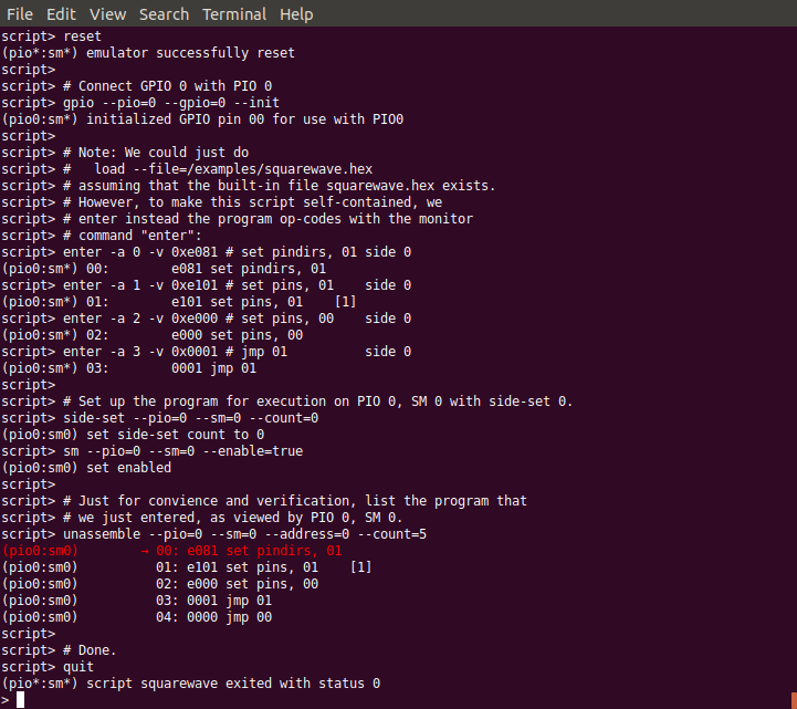
First, start a monitor session. Execute the example squarewave PIO
pogram monitor script with the command
script --dry-run=false --example squarewave (or, abbreviated,
sc -d -e squarewave). The script will start with resetting the
emulator such that we are in a well-defined state now, load the
squarewave example PIO program into PIO0, and set up SM0 of PIO0 for
execution of the program. The initial reset in the script will
also reset the clock cycle count to start with value 0 upon execution
of the next instruction.
Prepare Monitor for Debugging Session
squarewave monitor script will initialize the
emulator for debugging the squarewave example PIO program.Next, enter trace to execute the first instruction of the program.
This step will setup pin directions, and check the result with the
command gpio --pio=0 to see the pins at PIO0.
Setup GPIO Pin Directions
In another terminal window, we open a second instance of a monitor and
execute our ext-wave monitor script with the monitor command
script --dry-run=false --example=ext-wave. The script will
provide the external signal on GPIO 23. After startup, the script
stops at the first wait command in expectation for the PIO program
to arrive at clock cycle 2.
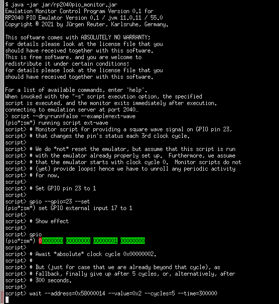
Start Monitor Script for Supplying External Signal
ext-wave monitor script will start the process of
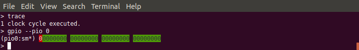
supplying an external signal.Now, in our first monitor instance, we enter the command
trace --show-gpio --pio=0 --wait=1000 --cycles=30 to let the
emulator perform 30 clock cycles in order to continue execution of our
PIO program for a while. Option --wait=1000 will insert a delay
of 1 second between clock cycles, such we can easier follow what
happens. Options --show-gpio and --pio=0 will show us the
GPIO pins for each cycle as seen by PIO0.
PIO Program Run With Synchronized External Signal Input
squarewave while our
ext-wave script provides external signal input. One can see
the perfect 2/3 time proportion between the toggling bit of GPIO 0
(first, red column) that toggles every 2nd cycle, and the toggling
bit of GPIO 23 (last green column in of the third group of columns)
that toggles every 3nd cycle.As we can see, the squarewave PIO program toggles GPIO pin 0 every
2nd cycle, while the synchronized external monitor script ext-wave
toggles GPIO pin 23 every 3rd cycle. In this example, there is, for
simplicity, no interaction between the external signal and the PIO
program. But in a real-world use case, the PIO program could read in
the bit that is provided by the external signal.
Summary
We have seen how to provide an external signal to the GPIO pins and keep it in sync with a PIO program, even if the PIO program is debugged in single-step mode, just by implementing a monitor script that supplies the external data at the expected pace.
Similarly, we could write a monitor script that e.g. writes data into the PIO’s FIFOs, and sync this data supply monitor script with the PIO program in the same way as we have done it for the external signal. This way, we can simulate the processor cores to deliver data to the PIO.
Yet, writing data supply monitor scripts can be tedious work. Future plans for the PIO emulator contain ideas for providing a client application that assists in creating data supply monitor scripts, e.g. by graphically editing an external signal and generating a proper monitor script.
Alternatively, a yet-to-be-written emulator client application also could directly interface the emulator via the socket API / register facade for supplying external data to the PIO at the correct pace, rather than generating and running monitor scripts.