FIFO Observer
The FIFO Observer is useful for monitoring the status of a state
machine’s FIFO. The contents of the FIFO can also be displayed in the
monitor application with the command fifo. However, similar to
the other observers, while in the monitor application, one would need
to actively run the fifo command over and over again, the FIFO
observer application updates automatically in regular intervals, thus
relieving the user from actively polling for the status all the time.
The application is available as Jar file and can be executed from the command line via
java -jar rp2040pio_fifoobserver.jar
with optional paramater -p to specify the server port to connect
to. Again, like as for the server, the default port is 2040, if
not specified on the command line.
TX and RX
For a selected state machine of a selected PIO, the FIFO observer
application displays the FIFO’s full memory contents as an array of 8
words, by default split into 4 words for the TX FIFO, and another
4 words for the RX FIFO. Remember that the TX FIFO is used
for letting the CPU cores transmit data to the PIO, while the RX
FIFO is used for receiving data from the PIO and making it
accessible for the CPU cores.
For enqueueing and dequeueing data, you can
- execute or trace a PIO program that executes
PUSHorPULLcommands orINorOUTcommands with activated automatic push or pull, respectively; - manually run the monitor
fifoto modify a FIFO (see Sect. fifo for details), - write a monitor script that pushes or pulls data at some specific point of time (see Sect. Interfacing With External Data for details),
- or, if available, run any other client application that allows for pushing or pulling data.
FIFO Observer Application
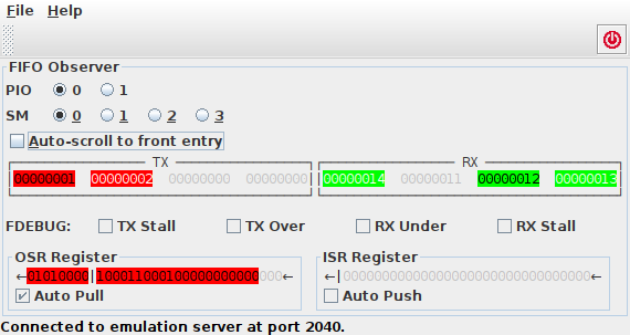
FIFOs may have a variable number of currently enqueued entries. That is, some of the memory entries may be currently unused. Currently unused entries are shown in gray text color on light gray background. Entries that contribute to the currently enqueued data are shown with colored background: red color for the TX FIFO and green color for the RX FIFO. People with red-green color defective vision may still differentiate between both FIFOs, since the RX and TX areas of memory are surrounded with a properly labelled border.
Autoscrolling
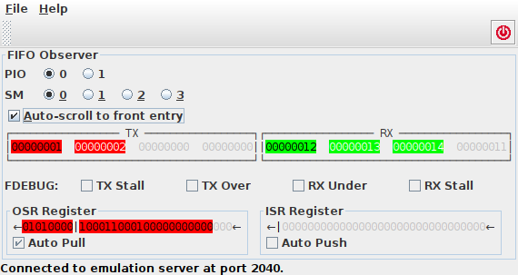
The FIFOs are internally organized as cyclic buffers. That means, there is a read pointer that points to the next the next word to be enqueued, and a write pointer that points to the memory location where the next word will be enqueued. If a FIFO is full, i.e. if all entries are currently used, there is no way to tell which of the entries is the next one to be dequeued, if you do not know where the read pointer currently points to. Therefore, the next word to be read is shown with black text color, while all other currently used entries are displayed with white text color.
Still, the view of the cyclic buffer may be confusing, in particular, when the currently used entries wrap around. Therefore, there is the display option Auto-scroll to front entry. If activated, the FIFOs’ contents is rotated such that the entry printed with black text color is aligned with the left-most word that is displayed. Dequeuing an entry will then, consequently, scroll all of a FIFOs entries one position to the left.
FIFO Observer Autoscroll Display Option
Joining
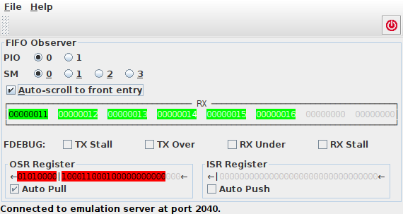
If only either RX FIFO or TX FIFO is needed, this FIFO may acquire all memory of the other FIFO – a concept that is called FIFO joining. Accordingly, the FIFO observer displays either both, TX FIFO or RX FIFO with each of them holding up to 4 words of memory, or only a joined TX FIFO or RX FIFO with 8 words of memory.
FIFO Joining
Similar to pushing and pulling, for join control, one can
- manually execute the monitor command
fifowith the--joinor--unjoinoption (see Sect. fifo for details), - execute a monitor script that performs joining or unjoining at specified points of time,
- or, if available, use any other client application that allows for joining or unjoining.
FDEBUG Bits
Each state machine features a number of bits that record exceptional states (FIFO overrun or underrun). The current state of these bits is displayed as read-only checkboxes beneath the FIFO panel.
OSR and ISR
While the FIFO is useful to temporarily store and shift around 32 bit
data words, just matching the RP2040’s 32 bit processor operations
of the ARM cores, GPIO pins work on a single bit level. To fill
this gap, there is the Output Shift Register (OSR) and the Input
Shift Register (ISR). These registers exchange complete 32 bit
words with the FIFO, but their ability for bit-shifting enables a
state machine to access any number of consecutive bits. When the
state machine performs a PULL operation, you may see a 32 bit word
being copied from the TX FIFO to the OSR (provided that the FIFO is
not empty). Similar, a PUSH operation will copy the contents of
the ISR into the RX FIFO. Operations OUT and IN will shift a
number of bits out of the OSR and into the ISR, respectively.
The fill level of OSR and ISR, that is, the number of bits being tracked as significant, is indicated by coloring all significant bits. Similar to the TX and RX FIFO entries, significant bits are displayed in red color (for the OSR) or green color (for the ISR), since the OSR is associated with TX, and the ISR with RX, respectively. All non-significant bits beyond the threshold are displayed in gray color, just like the unused entries in the FIFO.
The configuration of the autopull feature (for the OSR) as well as
of the autopush feature (for the ISR) is indicated by the state of
the corresponding checkbox aligned with the OSR or ISR.
For both, the OSR and ISR, there are arrows at the left and at the
right of the bit pattern. The arrows indicate the shift direction of
the shift register. The vertical line that appears somewhere in the
bit pattern (or in front or behind) indicates the threshold for
autopull or autopush operation: autopull will occur when
underrunning the pull threshold; similarly, autopush will occur
when overrunning the push threshold.