Diagram Creator
The Diagram Creator client application is used to create timing diagrams from a run of a PIO program. Given a set of signals to observe, the application lets the emulator run a number of clock cycles (starting from whatever current internal status of the emulator). After each cycle, the application records the new values of all of the currently displayed signals, until the number of desired cycles has been completed. Finally, it renders the corresponding timing diagram from the recorded data.
Just like all other client applications, Diagram Creator is available as Jar file and can be executed from the command line via:
java -jar rp2040pio_diagram.jar
with optional paramater -p to specify the server port to connect
to. Again, like as for the server, the default port is 2040, if
not specified on the command line.
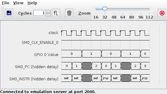
Diagram Creator Application
Recording
Clock cycles to be recorded for the diagram view are triggered by
selecting a number of cycles and then pressing the Cycle button
 . Note that the Diagram Creator intentionally
only records data when clock cycles are triggered explicitly from
within the Diagram Creator. It does not record clock cycles that
are triggered elsewhere, e.g. by the
. Note that the Diagram Creator intentionally
only records data when clock cycles are triggered explicitly from
within the Diagram Creator. It does not record clock cycles that
are triggered elsewhere, e.g. by the trace command from within a
Monitor instance. The rationale behind this design is as follows:
- The Diagram Creator requires time to process signal data while recording, and thus might miss clock cycles, if it would try to keep up with clock cycles arriving too fast. As a result, gaps would result in the recorded data, or the diagram could be even completely messed up (e.g. with data erroneously mapped to a wrong clock cycle).
- When detecting a gap in the emulator’s wallclock during recording, the Diagram Creator will clear the view and start from scratch, since a detected gap in time usually means that recording a new diagram has started. Assuming the Diagram Creator would react to externally triggered cycles, this behavior would imply that triggering a clock cycle from e.g. within a Monitor could accidentally clear the diagram view.
To avoid these flaws, the Diagram Creator only records clock cycles
that are triggered from within itself. More cycles may be appended to
the currently displayed diagram just by running some more cycles,
provided that there is no gap detected. If a gap is detected
(e.g. from executing the trace command in a Monitor instance
between the two emulation runs), the diagram view will be
automatically cleared before continuing with the next cycles.
To manually clear the diagram view, press the Clear button
 . Clearing the diagram view will also drop all data
that has been recorded so far.
. Clearing the diagram view will also drop all data
that has been recorded so far.
Rendering
For specific signal types such as PIO instructions, more detailed information, that does not fit into the narrow cells of the digram, is instead displayed with tooltips.
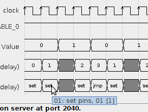
Diagram Tooltips Display
Via the View → Properties… dialog, the set of shown signals can be selected and deselected, and the order can be changed.
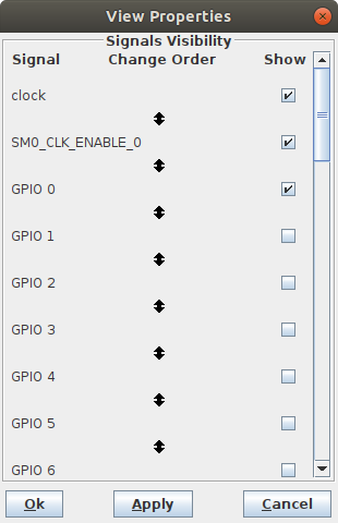
Visibility Control of Signals
Warning
The signal view properties dialog is subject to change. Currently, the available set of displayable signals is still limited and hard-wired. As of now, only visibility and display order of this fixed set of signals can be configured. This status quo is going to be replaced by a much more generic and freely configurable way to select register bits from the register facade and configure a renderer (out of a set of predefined renders) to apply on the selected bits.
Use the Zoom slider to adjust horizontal zoom, i.e. the time
scale, as it fits best for your needs. If the diagram grows large,
scrollbars will appear such that you can select what section of the
diagram you will view.
Note
Diagram export, e.g. as PDF, SVG or PNG file, is not yet implemented, but will be added some time in the future.
Setup
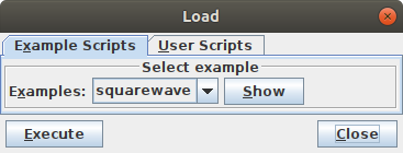
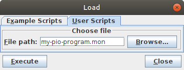
Via the File → Load… dialog, a monitor script may be executed in order to set up the emulator by loading a PIO program into a PIO’s instruction memory and configuring the emulator for executing it, such as properly setting up the state machines’ side-set for execution of that program. Some built-in example scripts are provided, but you can also write your own user-specific monitor scripts for execution for setting up the emulator.
 |
 |